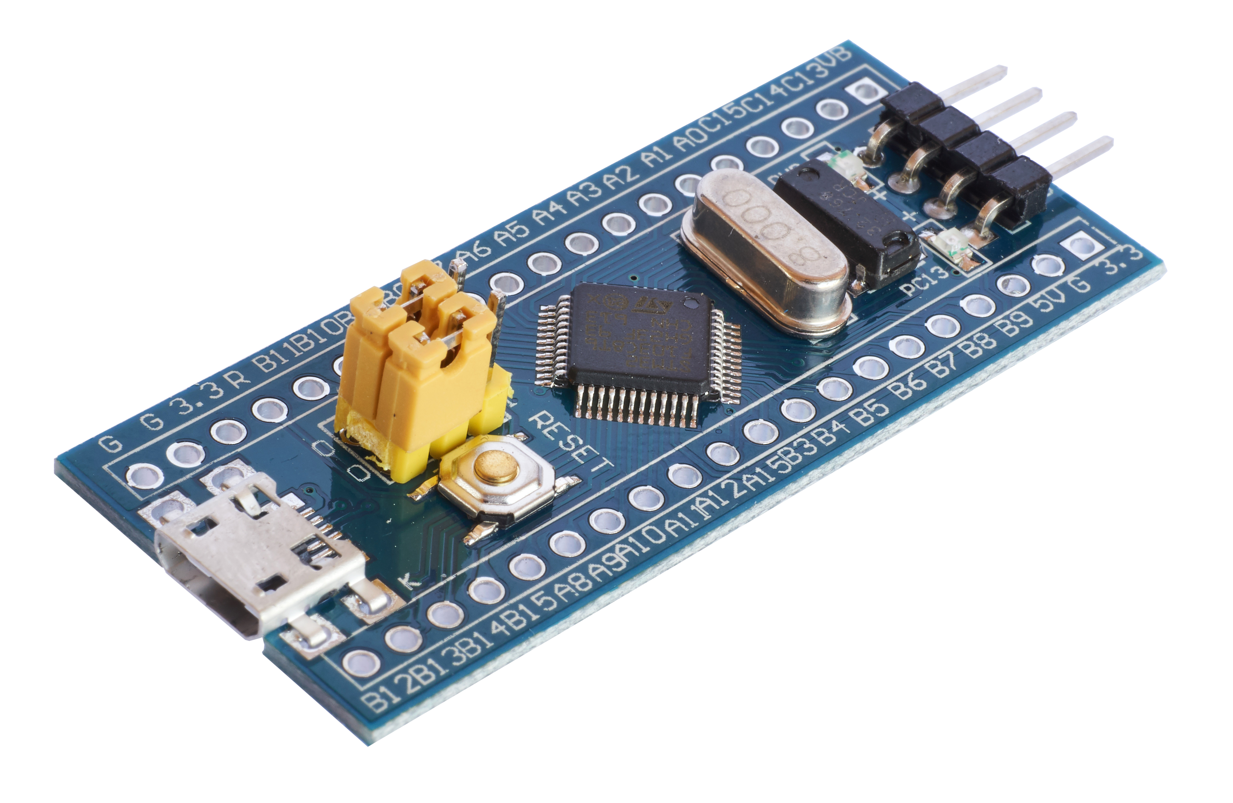
So I got me some of these off of ebay or aliexpress a while ago. Mostly I wanted them because they're about as cheap and small as an arduino nano, but on paper these small blue pills have way better specs. The only problem, and the reason it's taken me over a year to try again to get these boys running, is that they're not as convenient to use as arduinos. Bootloaders need to be flashed for USB programming to work, for example.
1Specs and comparison vs Arduino Nano
| Device | Blue Pill | Arduino Nano |
|---|---|---|
| MCU | STM32 F103 | ATmega328 |
| Core | ARM Cortex-M3 32bit | AVR RISC 8bit |
| Freq. | 72 MHz | 20 MHz |
| Flash | 64 kB | 32 kB |
| SRAM | 20 kB | 2 kB |
| PWM Res. | 16 bit | 10 bit |
| ADC Res. | 12 bit | 10 bit |
| GPIOs | 32 | 24 |
| PWM Channel | 15 | 6 |
| Analog Channel | 10 | 8 |
| I2C Buses | 2 | 1 |
| SPI Buses | 2 | 1 |
| CAN Bus | Yes | No |
2IMPORTANT
If using the ST-Link V2 programmer for flashing/debugging and USB for serial input/output at the same time, make sure to disconnect the VCC line from the programmer, as power will be supplied by the USB.
3Flashing
4STM32Duino
Ok so, unlike an Arduino, these chips aren't exactly plug-and-play out of the box. Following are the steps I had to take to get them programmable and running on par with an Arduino using STM32Duino. By flashing the STM32duino bootloader, we'll be able to upload Arduino sketches via USB in the Arduino IDE.
In all steps of the process, the STM32duino wiki has been a great help!
4.1Step 1: Install stlink
On arch, the package is just called stlink and provides the
stlink-gui application we'll use to flash shit.
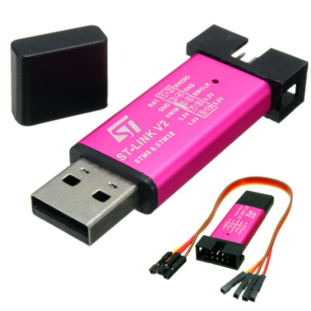
4.2Step 2: Get hold of a ST-Link V2 programmer
They look like this.
4.3Step 3: Configure STM32 boot pins
To allow us to flash the board, set pin Boot0 to state 1. Leave Boot1 at false. Boot0 is the one of the two boot-pins furthest from the reset button.
4.4Step 4: Connect the device to the programmer to the PC
Connect SWCLK, SWDIO, GND, 3.3V pins from programmer to corresponding
pins (Note: probably not in the same order) on the side-angled 4-pin
header on the board. Like in this
image. 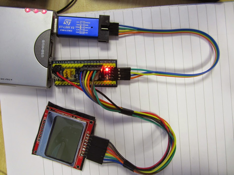 . Then connect the programmer to
PC via USB.
. Then connect the programmer to
PC via USB.
4.5Step 5: Flash bootloader
Open stlink-gui and press the connect button. Some information about
the device should show in a box. If it says something like "device:
unknown" and "memory size: 0", something's wrong. Maybe it's the
existing bootloader? Try erasing with st-flash erase. Maybe the
microcontroller is broken? No luck then.
Still in the GUI, open the bootloader file. Can be found at https://github.com/rogerclarkmelbourne/STM32duino-bootloader/tree/master/binaries. I used genericboot20pc13.bin. Then flash the image to memory address 0x08000000 (should be default suggested).
4.6Step 6: Disconnect
Disconnect the device first in the GUI, then physically. Set Boot0 pin to 0. We should be all good to go now!
4.7Step 7: Verification
To check that the flashing worked as expected, connect the stm32 via it's on-board USB, and read its serial output, e.g. with "screen /dev/ttyXXX". If the flashing was successful, we should read a repeating message:
Congratulations, you have installed the STM32duino bootloader
See https://github.com/rogerclarkmelbourne/STM32duino-bootloader


For more information about Arduino on STM32
and http://www.stm32duino.com
4.8Step 8: Setup arduino etc
Cba writing this part, but it's all on the wiki.
On my linux PC, I had some problems with errors along the lines of "dfu cannot open device". I didn't manage to fix this, but installing all the necessary drivers on Windows did the trick.
4.9Done!
But I don't think I'll use them this way. Arduino is not as fun as Rust ;)
5Rust
5.1Step 1: Install rust target
rustup target add thumbv7m-none-eabi
5.2Step 2: Setup cargo project
Set project file Cargo.toml to something like this:
[package]
name = "stm32_blink"
version = "0.1.0"
edition = "2018"

[profile.release]
# optimize for size ('z' would optimize even more)
opt-level = 's'
# link with link time optimization (lto).
lto = true
# enable debugging in release mode.
debug = true

[dependencies]
# Gives us access to the STM32F1 registers
stm32f1 = {version = "0.6.0", features = ["stm32f103", "rt"]}
# provides startup code for the ARM CPU
cortex-m-rt = "0.6.7"
# provides access to low level ARM CPU registers (used for delay)
cortex-m = "0.5.8"
# provies a panic-handler (halting cpu)
# (required when not using stdlib)
panic-halt = "0.2.0"
The cortex-m-rt crate also requires a memory.x file, which specifies
the memory layout of the board. The documentation already provides the
file for the BluePill as an example, so we only have to create the
file memory.x with the following content:
/* Linker script for the STM32F103C8T6 */
MEMORY
{
  FLASH : ORIGIN = 0x08000000, LENGTH = 64K
  RAM : ORIGIN = 0x20000000, LENGTH = 20K
}
Create file .cargo/config with the following content:
[build]
# Instruction set of Cortex-M3 (used in BluePill)
target = "thumbv7m-none-eabi"

rustflags = [
  # use the Tlink.x scrip from the cortex-m-rt crate
  "-C", "link-arg=-Tlink.x",
]
5.3Step 3: Example program
Here is an example Blink program. Set src/main.rs to the following:
// std and main are not available for bare metal software
#![no_std]
#![no_main]

extern crate stm32f1;
extern crate panic_halt;
extern crate cortex_m_rt;

use cortex_m_rt::entry;
use stm32f1::stm32f103;

// use `main` as the entry point of this application
#[entry]
fn main() -> ! {
    // get handles to the hardware
    let peripherals = stm32f103::Peripherals::take().unwrap();
    let gpioc = &peripherals.GPIOC;
    let rcc = &peripherals.RCC;

    // enable the GPIO clock for IO port C
    rcc.apb2enr.write(|w| w.iopcen().set_bit());
    gpioc.crh.write(|w| unsafe{
        w.mode13().bits(0b11);
        w.cnf13().bits(0b00)
    });

    loop{
        gpioc.bsrr.write(|w| w.bs13().set_bit());
        cortex_m::asm::delay(2000000);
        gpioc.brr.write(|w| w.br13().set_bit());
        cortex_m::asm::delay(2000000);
    }
}
5.4Step 4: Creating the binary
Compile with cargo build --release.
5.6Step 5: Flash / debug
Update: Check out cargo flash as an alternative to stlink. Should
be easy to use, just cargo flash --chip stm32f103C8 --release.
Install stlink. Run st-util to automatically connect to the STM32
and start a GDB server at some port. Tip: st-util seems to die every
time GDB disconnects, so maybe run it in a while loop, like while
true; do st-util; sleep 1; done.
Open your compiled rust-program in GDB with
arm-none-eabi-gdb -q target/thumbv7m-none-eabi/release/ELF_BINARY_NAME,
then connect to the server with (gdb) target remote :PORT. Finally,
flash the binary with (gdb) load, and you're ready to debug!
The program starts stopped at its entry point. To just run the
program, enter (gdb) continue. Otherwise it's like normal GDB
debugging!
Tip: Start GDB in emacs with command gdb and command
gdb -i=mi -q ../target/thumbv7m-none-eabi/debug/ELF_BINARY_NAME -ex "target remote :4242".
Note: Debugging seems to be really buggy when I've tried it. load,
monitor reset halt, and continue all seem to work, but
breakpoints, backtrace, and stepping seems quite broken. A better
method of debugging is probably good-ol print debugging via serial
port.